

Home
About Us
Contact Us
Customer Reviews
Questions? We Can Help

Spec’s and Owner’s Manual
Spec’s and Owner’s Manual
Owner’s Installation & Operations Manual
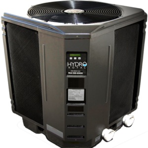
For Hydro Royal Heat Pump

Note from Hydro Royal:
This Owner’s Manual refers simultaneously to Swimming Pool, Spa, and Aquaculturetank applications. If you have any questions please contact Hydro Royal at (888)205 7766.
5005001B
Version 2.02
Page 2
TABLE OF CONTENTS
3 | |
5 | |
5 | |
5 | |
6 | |
6 | |
7 | |
8 | |
9 | |
10 | |
10 | |
10 | |
11 | |
11 | |
11 | |
11 | |
11 | |
12 | |
12 | |
12 | |
13 | |
15 |
Page 3
Congratulations on purchasing the most advancedhigh efficiency,
microprocessor-controlled pool , spa andAquaculture heat pump available. Your heat pump has been manufactured with themost state-of-the-art quality control
equipment available today to ensure the highestquality product delivered to
your door. A heat pump water heater is a highlyefficient, cost effective
method of water heating. Proper operation andcare will result in many years
of worry free heating or cooling depending on themodel you chose .
Your new heat pump is a self-contained unitdesigned specifically for
swimming pool and spa heating and can be used foraquaculture applications
when installed properly. It utilizes the sun’s free energy by
extracting heat from the sun-warmed air andtransferring it efficiently to the
pool/tank water. Because your heat pump moves thefree heat from the
outside air to the pool/tank, rather than createheat, as a fossil fuel or electric
resistance heater does, it can heat yourpool/spa/tank for up to
80% less cost than these other less efficientmethods.
As with all water heating methods, you are advised to utilize a cover at
night. The cover should be used if the nighttemperature is 15°F (8°C)
less than the desired water temperature.
This will keep evaporation, the greatest sourceof heat loss, to a minimum,
greatly reducing the overall heating costs.During warmer weather,
the cover may not be required.
Your pool/spa/tank heat pump combines simplicitywith trouble-free
performance. As with most appliances, anunderstanding of proper
operation of the heat pump is important. Properinstallation and operation
increases efficiency and reduces operating costs.Your heat pump is
designed with features that make it simple tooperate, maintain and service.
Proper installation enhances these features andminimizes problems. This
manual will provide you with the informationneeded to properly install,
operate and maintain your heat pump.
Page 4
Please be sure to complete and mail in theWarranty Registration Card that
is provided in the package with your heater. Thiscard helps us to notify
you about new information on your heater.
Also, please take a moment and jot down thefollowing information. If you
should ever need to call us for service or aquestion, we will need this
information:
Model Number:___________
Serial Number:___________
Purchase Date:___________
Dealer Name/Address/Phone#:________
____________
Page 5
The unit is designed for outdoor installation andshall not be placed in a
totally enclosed area such as a shed or a garageunless ventilation is
provided to ensure adequate air exchange forproper operation.
Recirculation of cold discharge air back into theevaporator coil will greatly
reduce heating capacity and efficiency of theunit and void the compressor
warranty.
The heat pump should be located as close aspractical to the existing pool/tank pump
and filter to minimize water piping length. Theuse of 90° bends and short
radius elbows in the water piping should belimited to keep water pressure
drop to a minimum.
Your heat pump features an up-flow fan for quietoperation. Air is pulled
through the evaporator coil and dischargedthrough the top grill. At least 4
feet clearance should be allowed above the unitfor unrestricted air
discharge. The unit must not be installed under aporch. Any side of the
unit should be located at least 12 inches from awall or other obstruction for
unrestricted air intake and service access.
Mount the unit on a flat, level surface,preferably a concrete or fabricated
slab. The unit should be completely isolated fromthe building foundation or
wall to prevent the possibility of sound orvibration transmission into the
building. The base of the unit may be used tofasten to if local codes
require securing the unit to the slab.
Make sure that there are no sprinkler heads nearor directly spraying into
the heater. Cap off or redirect heads as needed.
The unit can be strapped down using a strap kit.Attach a
strap to each side and anchor to the deck.
Page 6
The piping sequence: pool/tank pump / filter /heat pump / chlorinator (if pool) / pool/tank.
Note for Pools:
In-line chlorinators must be down stream of theheater to minimize harm to the
pool equipment.
Rigid PVC piping is recommended and all jointsshould be
secured with PVC glue. Make sure that thedirection of the water flow
through the heat pump is correct as indicated bythe labels on the unit. When
the piping installation is complete, operate thepool pump and check the
system for leaks. Check the filter pressure gaugeto ensure that excessive
pump head pressure is not indicated.
The recommended flow rate is 50 gpm through theheat pump.
For questions on multiple unit installations,please contact our
main office. Multiple unit installations shouldalways be in
parallel circuits.
CAUTION: The main power disconnect must be offbefore opening the
access panel.
It is required that the wiring of your heat pumpbe done by a qualified
electrician in accordance with local coderequirements.
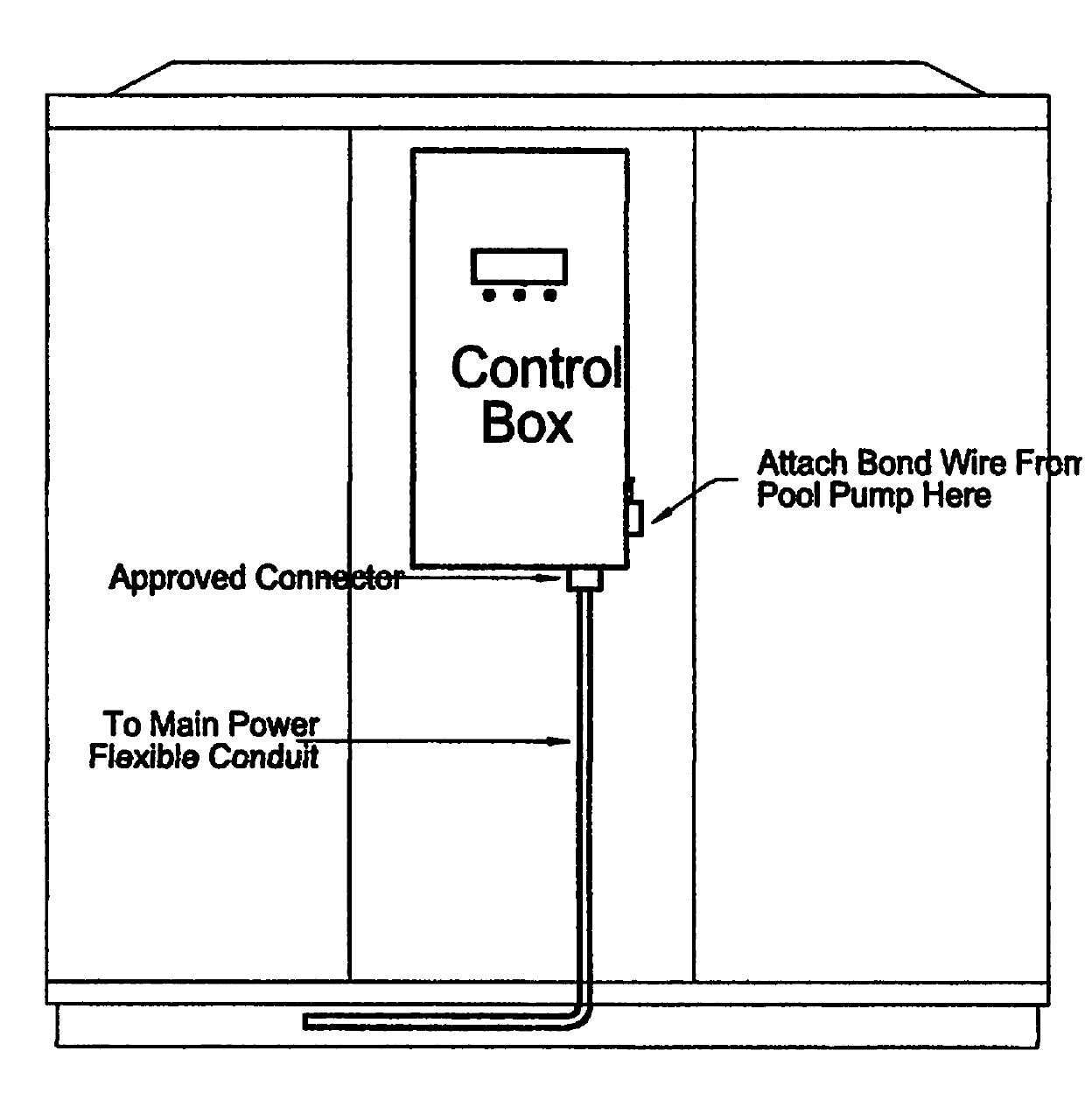
IMPORTANT: The electrical conduit must be run upthrough the base of
the unit and connected at the control box with aconduit connector.
A properly sized breaker and copper wire must beused. See inside access
panel for wiring diagram.
Page 7
Because all metals have different electricalpotentials, ALL metal
and electrical components of the pool/tank systemmust be bonded
together. This includes the metal framework ofthe pool/tank, lights, pump,
filter, heater, any automatic chlorine generatorand any other metal or
electrical equipment. On some older pools, thissubstructure bond wire may
not exist. In this case, a 6 to 8 ft. copper rodmust be driven into the
ground near the pool/tank equipment and allelectrical and metal components
must be bonded to the rod. A bonding lug isfurnished on the side of the
control box of the heat pump for the bond wire tobe attached. Warranty will
be void if system is not properly bonded.
Page 8
Not only is the water chemistry of your pool, spaor tank important to human health
or livestock health, it also directly affects thelife of your heat pump. This is
the most important item in the maintenance of theheat pump. If the water
chemistry is improperly maintained or if thechemicals are improperly
introduced into the water, this will damage theheat pump’s internal heat
exchanger and could eventually cause a leak,rendering the heat pump
inoperable.
CAUTION: Damage to the heat pump due to improperwater chemistry
is not covered under the warranty.*
Following is the table for essential waterquality readings, which must be
constantly maintained for swimming pools andspas:
Description | Normal Range | Verify |
PH Level | 7.4 to 7.8 | 1 time per week |
ChlorineConcentration | 1.0 to 3 PPM | 1 time every 2 to3 days |
Total Alkalinity | 80 to 120 PPM | 1 time every 2 to3 weeks |
Total DissolvedSolids | Below 2400 PPM | 1 time per month |
Calcium Hardness | 200 to 300 PPM | 1 time per month |
The location of the chemicals’ introduction toyour system is also critical to
the heat pump’s life. If an automatic in-linechlorinator or brominator is used, it
must be located downstream of the heat pump. Atrap must also be installed
between the chlorinator and the heat pump toprevent chlorine return into the
heat pump.
Note for Swimming Pools andSpas:
IMPORTANT: Never leave any type of solid chlorinein the pool skimmer.
This will cause a high concentration of Chlorineto enter the heat pump, causing
premature corrosion. You must divert water flowdirectly to the pool/tank before
adding fast dissolving chemicals in skimmer.
* Models with Titanium Tube heat exchangers donot have a water
chemistry exclusion in their warranty.
Page 9
CABINET –Your heat pump’s cabinet is made from a maintenance-free,
rust-free plastic that is UV resistant. It willlast for years and any dirt or
dust may simply be wiped away with a cloth orsprayed off with a water
hose. The use of a product such as Armor- Allwill restore its natural luster.
DO NOT USE CLEANERS THAT CONTAIN ALCOHOL.
CONTROL –State-of-the-art LCD readout control. Displays mode and
temperature of the water for ease of operation.No programming to learn.
Dual thermostats allow user to set pool, spa ortank temperatures. The control
is self-diagnostic and will display a fault ifthere is a problem. Other
features include: lockout, spa timer, automaticlow temperature defrost and
remote control capabilities.
ULTRA-QUIET –The unit is equipped with a low RPM fan motor in
combination with a deep drawn venturi to ensurewhisper quiet operation.
HIGH EFFICIENCY –The heat pump utilizes the latest in compressor
technology to produce the highest efficiencyavailable when coupled with
the over-sized enhanced fin evaporator coil.
EASE OF INSTALLATION –The unit is equipped with easy-to-install,
hand-tightened unions for a quick andtrouble-free installation. The unions
will accept 2″ PVC piping. The electricalconnection is made with one entry
directly into the control box for a quick hook-upand a neat appearance.
EASY ACCESS –The heat pump was designed for quick and easy access for
installation and diagnosis. The service panel isremoved with two screws
and access to all service connections is right upfront and easy to reach.
This allows the installation and service to bedone quickly and efficiently –
so valuable time is not wasted.
Page 10
When the unit is powered up, but in the OFF mode,the display will show
“OFF”. To turn the unit on, press the Up arrowbutton until desired
temperature is reached. To turn the unit offpress and hold the Down arrow
button until the display shows off. This pointwill be one level below 50
degrees. This is convenient for shutting the unitdown for short periods of
time.
CAUTION: When the control is in the “OFF” mode,there is still high
voltage to the unit. If you want to turn the unitoff for long periods of time,
shut the main power off to the unit at the mainor service disconnect.
The control is equipped with two independentthermostats, one for pool
temperature and one for spa temperature in caseof swimming pool application.
This is to allow the user to preset a temperature of their choice and switch
between the two settings with the POOL/SPA button located on the control.
When power is applied to the control it will turn on in the previous mode,
whether it is Pool Heat or Spa Heat.
When water is flowing through the unit and the water temperature meets
the specified set point condition, the controlwill initiate a heat cycle.
If you do not have a spa, you can use the spathermostat as a second
temperature setting if you do not want tomaintain full temperature all the
time. For instance, if you swim on the weekendsonly, you can set the
temperature back during the week to save costsbut maintain a warmer
temperature for a shorter recovery time for theweekend.
ATTENTION:There is a 5-minute time delay upon completion of a
heating/cooling cycle. This is to ensure that the critical components do
not fail due to short cycling of the heat pump.
The display on the control will show thethermostat being used and the
operating mode on the top line and the currentwater temperature on the
bottom line. The possible mode displays are:“POOL – HEAT”, “SPA –
HEAT”.
Page 11
CHANGING SET POINT TEMPERATURE
To change the set point temperature, press eitherthe Up or Down arrow
buttons on the control. The display will thenshow “POOL TEMPERATURE”
on the top line and the current set pointtemperature in numbers on the
bottom line. After adjusting to the desiredtemperature setting, the display
will revert to “POOL – HEAT” (or whichever modeyou are in) on the top line
and the pool temperature in numbers with“DEGREES” on the bottom line
after 5 seconds of inactivity and the new setpoint will be stored in memory.
The default factory setting for Pool temperatureis 85 degrees Fahrenheit.
The owner is responsible for determining thenecessary length of operating
time for the pump and heat pump based upon theirparticular requirements.
Most units are sized to operate during thepool/tank filtering cycle time of 8 to 12
hours daily, providing an even, steady flow ofheat. On warmer days the
heat pump will run less because there will beless heat loss from your pool/tank. The
heat pump is capable of running 24 hours per dayif necessary. When you first
run your heat pump, it may need to runcontinuously for 24 to 48 hours to get
the pool/tank up to the desired temperature.
While in any mode the user can lockout the keypadby pressing and holding
the POOL/SPA button for 6 seconds. When thekeypad lockout has been
enabled all buttons are disabled and the controlwill operate in whatever
mode it was in when the lockout occurred. Anybutton push while in lockout
will cause the display to show LOCKOUT for 5seconds. To unlock the
Keypad, press and hold the POOL/SPA button for 6seconds. The display will
show UNLOCKED for 5 seconds.
The heat pump is designed to enter the defrostcycle at ambient air
temperatures below 48° Fahrenheit. During thiscycle, the unit may shut
down and the control will display “Defrosting”until the ambient air
temperature rises above frosting conditions.
It is normal for water to be draining from yourheat pump. This occurs because
the evaporator coil condenses the water from theair. The water drains into
the base of the unit and out the holes that arelocated on each side of the
heater at the bottom. Your heat pump can produce1 to 3 gallons of water per
hour. The water created from the condensationwill dry up when the heat pump
shuts off.
Page 12
There is not much maintenance that needs to bedone on your heat pump.
Making sure there is good airflow through theevaporator and proper
drainage are the two main tasks. A garden hosewith low-pressure water
flow can be used to clean the evaporator coil.Make sure the heat pump has good ventilation to allow sufficient airflow.
CAUTION: Make sure all power is disconnected tothe heat pump prior
to washing.
Clean the coil as needed. If located near theocean, cleaning will need to
be done regularly to remove salt and sand. Use avery soft brush so as not
to bend the coil fins with soapy water to removeany build up. Keep the
drain holes in the base free of debris to assureproper condensate
drainage.
Your heat pump’s cabinet is made from amaintenance-free, rust-free plastic
that is UV resistant. It will last for years andany dirt or dust may simply be
wiped away with a cloth or sprayed off with awater hose. The use of a
product such as Armor- All will restore itsnatural luster.
DO NOT USE CLEANERS THAT CONTAIN ALCOHOL.
Alcohol based cleaners may damage the plastic.
In areas where freezing condition is notprevalent and winterizing of pools is
not common, allow water to flow through the heatpump even when not in use.
In freezing areas, it is mandatory that the waterbe completely
drained from the heater and disconnected from thepiping. The
heat exchanger must be blown out with air toensure no water in
the heat exchanger.
Page 13
A simple test to verify that your heat pump isfunctioning is to place your hand
above the unit. There should be cool air blowingout the top after time
delay has expired. The return water to thepool/tank should be a few degrees
warmer than water entering the heater. Afterabout 15 minutes of run
time, there should be water draining out of thebase of the unit.
If you have reason to believe your heater is notfunctioning properly, follow
the troubleshooting guide below or call thefactory for service.
CONDITION | POSSIBLE CAUSE | POSSIBLE SOLUTION |
Control Display Blank
| No power supplyto heater. Trippedbreaker or blown fuse.Control failure. | Reset breaker.Replace fuse. If problempersists, call factory forservice. |
Control Displays “LOW FLOW”
| The pool pump isnot on. A valve isturned, bypassing thewater through the heatpump. Clogged waterline, filter or pumpimpeller. Internal waterpressure switch failure. | Turn pool pumpon. Clean pump and filter.Adjust water valves. Ifproblem persists, callfactory for service. |
Control Displays “DEFROSTING” | Ambient air istoo low for heat pump tofunction.
| Unit will turnback on once ambient air risesto appropriatelevel.
|
Control Displays “LOW REFRIGERANT PRESSURE”
| Refrigerant leak. | Call factory forservice. |
Page 14
Control Displays “HIGH REFRIGERANT PRESSURE”
| Water flowrestriction, valve is turned restricting flow. | Clean pump andfilter. Adjust watervalves. If problem persists,call factory forservice.
|
Control Displays “HP3 Water Lockout”
| Water flowrestriction, valve is turned restricting flow.
| Clean pump andfilter. Adjust watervalves. If problem persists,call factory forservice.
|
Control Displays “HIGH WATER TEMPERATURE”
| Heater control malfunction.Secondary source of heat.
| Call factory forservice.
|
Control Displays “EVAP SENSOR MALFUNCTION” | Defrost sensor malfunction ornot connected.
| Call factory forservice.
|
Control Displays “WATER SENSOR MALFUNCTION” | Water sensor malfunction ornot connected. | Call factory forservice. |
Pool/tank isheating or chilling slowly or not getting up to temperature. | Low or restrictedwater flow through the heat pump. Leakin plumbing allowingair into the waterflow. It is cold outside.Pump timer is not set for a long enough runtime. Pool is not being covered. Highwind speed overpool/tank. Pool/tank area shaded. | Clean or replacefilter. Inspect and cleanpool pump. Adjustwater valves. Repair air leaks.Use a pool cover. Constructa wind break aroundpool/tank. Set pool pump timerlonger. Call factory forservice. |
Water is running out of the bottom of the heat pump.
| The heat pumpproduces up to 3 gallons perhour of water condensingfrom the evaporatorcoil. Internal waterleak.
| Shut the heatpump off for several hours andleave the pool pumprunning. If the water is stillrunning out, call factory forservice.
|
Page 15
All service must be handled by an AuthorizedService Center. Warranty may
be void if a non-authorized servicerepresentative does service. Do not
return the heat pump to your dealer, as they donot provide service.
Before calling for assistance or service, pleasecheck the Troubleshooting
section of this manual or call your dealer. Thismay save you the cost of a
service call. If you still need help, follow theinstructions below.
Service can be obtained by calling us at: (888)205-7766 and we will transfer you to the Authorized Service Center.
When asking for help or service please provide adetailed description of the
problem, your heat pump’s complete model numberand serial number, the
purchase date and dealer purchased from. Thisinformation will help us
respond properly to your request.
Keep a copy of the sales receipt showing the dateof purchase.
Proof of purchase will assure you of in-warrantyservice.
MANUFACTURED BY:
G & F MANUFACTURING, INC.
The Hydro Royal Heat pumps can be used forAquaculture purposes. Certain installation conditions must be met so thatmanufacturer’s warranty will not be void for product misuse and/or improperinstallation. When installing your unit make sure that you have the adequatewater pump and filter for your application. The risk of clogging your heatexchanger is higher if you don’t have the right filter for your system.
G & F Manufacturing will not be responsible for heat pump damage occurredbecause of improper operation and installation.
Please contact us before installation at 1 888205 7766 for advice.